
Electronics mounted on a vehicle, machine or robot are shaken for their whole life. The failures look random — an intermittent connection, a cracked solder joint, a capacitor that falls off — but they follow from predictable mechanisms. Designing for vibration costs little early; testing finds what was missed.
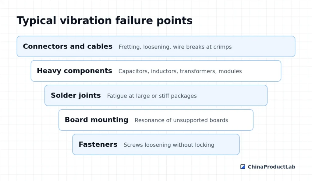
Where failures happen
Design measures
- Locking connectors; avoid board-to-board connectors carrying heavy boards
- Strain relief and clamping for cables, close to connectors
- Adhesive staking for heavy or tall components
- Mounting points near heavy parts; stiffen boards to move resonance up
- Thread locking for screws
- Potting or encapsulation for severe environments (trade-off: repair and heat)
- Heavy parts with through-hole or mechanical support where needed
Testing
| Test | Purpose |
|---|---|
| Resonance search (sine sweep) | Find natural frequencies of boards and brackets |
| Random vibration | Simulate real-world vibration profiles |
| Mechanical shock | Drops, impacts, bumps |
| Combined with temperature | Reveal solder fatigue and connector problems faster |
Profiles come from application standards (for example IEC 60068-2 test methods, and industry-specific standards for vehicles or rail) or from measurements on the real machine. Run units powered and monitored, so intermittent faults are caught during the test, not only afterwards.
Power and environment in vehicles
Vehicle-mounted electronics also face electrical stress: voltage drops during engine start, load dumps, reverse polarity and noise from motors and ignition. Automotive and industrial standards define these disturbances. Even for aftermarket and machine-mounted products, design the power input to survive them with protection components and wide input ranges.
Temperature is the third factor: dashboards and engine bays reach high temperatures, while outdoor machines see cold starts. Combine vibration testing with temperature extremes where possible, because materials and solder joints behave differently when hot or cold. Seal connectors against dust and water, since contamination accelerates fretting and corrosion under vibration.
Mounting the product
How the product is mounted affects the vibration it receives. Rubber isolators can reduce high-frequency vibration but may amplify low-frequency resonance if poorly chosen. Specify mounting points, fastener types and torque in installation instructions. For products installed by customers, include mounting hardware that is suitable for the environment, so that the tested configuration is the one used in the field.
Learning from field returns
When units return from the field, inspect them for vibration signatures: fretting marks on connector contacts, cracked solder joints at heavy components, loose screws and chafed cables. Record findings per failure and location. Patterns often point to a single design detail — a missing clamp, a heavy capacitor without adhesive — that can be fixed in the next production batch and added to the design checklist for future products.
Production consistency
Vibration robustness depends on assembly details: adhesive applied as specified, cables routed and clamped the same way, screws torqued. Put these steps in work instructions with photos and include them in inspection. A design that passed qualification can fail in the field if one batch skips the staking adhesive.
Related: wire harness specification, box build assembly and automotive.