A stripped thread is a small part of the product and a large part of the returns. Screw bosses that crack, threads that wear out after a few service openings, inserts that spin — most are decided by one early choice: how the thread is made.
Options compared
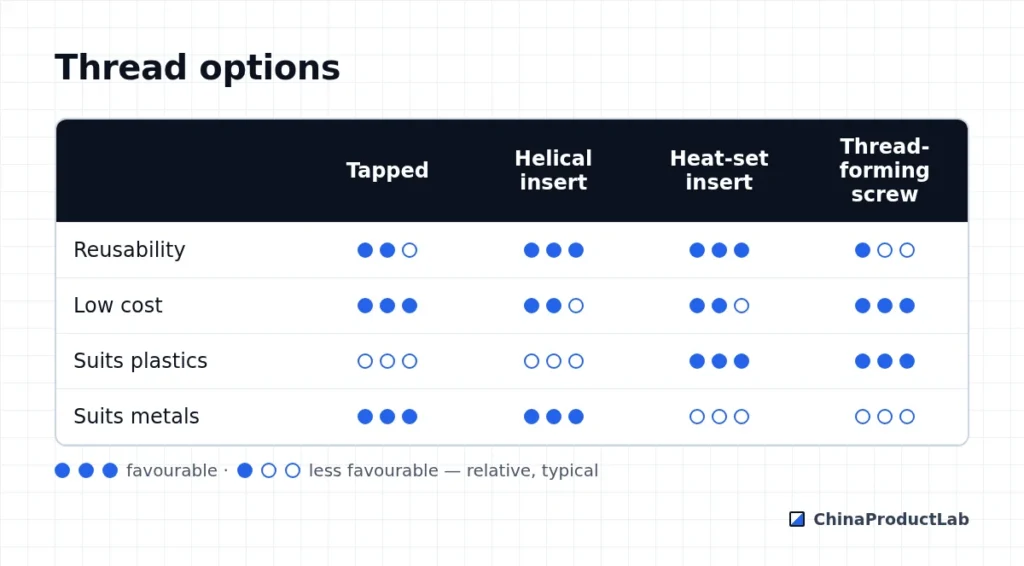
| Method | Material | Strength / reuse | Notes |
|---|---|---|---|
| Tapped thread | Metals | Good in steel; aluminum wears with frequent reuse | Specify thread class and depth; avoid blind holes tapped to the bottom |
| Helical coil insert | Aluminum, soft metals | High, repeatable | Common for parts that are opened often or need repair |
| Heat-set insert | Thermoplastics, 3D prints | Good | Pressed in with heat after molding; needs correct hole size |
| Molded-in insert | Thermoplastics | Very good pull-out and torque | Increases molding cycle and tooling complexity |
| Press-fit / ultrasonic insert | Thermoplastics | Medium to good | Fast assembly |
| Thread-forming screw | Plastic bosses | Limited number of re-assemblies | Cheapest; boss design is critical |
Plastic boss rules (typical)
- Outer diameter around 2–2.5× the screw diameter
- Boss wall thinner than the nominal wall to avoid sink; core out and connect with ribs
- Radius at the base; avoid sharp corners that start cracks
- Hole size from the screw or insert supplier’s data for that resin
- Lead-in chamfer and enough depth for screw engagement
- Glass-filled or brittle resins need extra care with hoop stress
Common thread failures and their causes
- Stripped plastic threads — boss hole too large, assembly torque not defined, or repeated reassembly with thread-forming screws
- Cracked bosses — hole too small, sharp corners, brittle resin, or weld lines at the boss
- Spinning inserts — wrong hole size for heat-set inserts or insufficient knurl engagement
- Galling in stainless — stainless screws in stainless threads without lubrication or anti-seize
- Worn aluminum threads — frequent service access without helical inserts
Test threads the way the product will actually be used: assemble with production screws and drivers, apply the defined torque, repeat the expected number of service cycles, then check pull-out and stripping torque. Do this on production-intent parts, because 3D-printed or machined prototypes behave differently from molded ones.
Choosing for the product life
The right thread solution depends on how often the joint will be opened. A battery cover that users open regularly needs metal threads — inserts in plastic, or helical coil inserts in aluminum. A housing closed once at the factory and opened only for repair can use thread-forming screws in plastic bosses, which is cheaper and faster.
Consider also who opens the product. Service technicians may use power tools and higher torque; consumers may use whatever screwdriver they have. Specify a screw head and drive that resists cam-out, and define whether the joint must survive a certain number of service cycles. Write this requirement into the product specification so that it is tested in validation, not discovered in field returns. When in doubt, a quick torque-to-failure test on a few production-intent samples gives a clear answer.
Specifying threads
Call out thread size, pitch, class (e.g. M3×0.5-6H), depth of full thread and the insert part number where used. Define assembly torque — overtightening is a frequent cause of stripped plastic threads.
Related: injection molding design rules, machining tolerances and insert molding. Ask for a DFM check.