A 3D model shows the shape. It does not say which surfaces are cosmetic, which holes are critical, what finish is required or which revision is current. When information is missing, a supplier fills the gap with their own standard practice — reasonable for them, but not necessarily what your product needs. A complete 2D drawing (or a fully annotated 3D model) is the contract for what will be made and inspected.
Drawing checklist
| Element | Why it matters | If missing, suppliers usually assume |
|---|---|---|
| Part number and revision | Prevents wrong-version production | Whatever file they received last |
| Material and grade | Strength, corrosion, cost | A common equivalent |
| Finish and color | Appearance and protection | Standard finish or none |
| General tolerance standard | Covers all untoleranced dimensions | Their shop standard |
| Critical dimensions | Tells inspection what to measure | Everything equal — or nothing in particular |
| Cosmetic surfaces | Defines where marks are not acceptable | Ejector marks and gates wherever convenient |
| Threads and inserts | Size, class, depth, part number | Nearest standard thread, full depth |
| Edge breaks | Safety and handling | Sharp edges or random chamfers |
From model to drawing to part
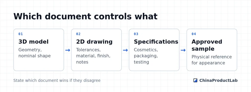
Agree a precedence rule — for example, “the drawing takes precedence over the 3D model for tolerances and notes” — and write it on the drawing. Conflicts between documents are common after quick design changes.
Notes that save rework
- Remove burrs, break sharp edges (with a value)
- Surface roughness for functional faces
- Cosmetic class or reference to a cosmetic standard
- Marking: part number, date code, cavity number location
- Protection: no scratches on cosmetic faces, packaging requirements
- Applicable standards, e.g. thread standard, general tolerance standard
- Inspection: critical-to-function dimensions flagged
Drawings for different processes
The checklist applies to all processes, but each adds its own essentials. Molded parts need draft direction, parting line and gate areas where cosmetics matter, ejector-pin keep-out zones, and the material grade including color. Sheet-metal drawings need the flat pattern or bend allowances agreed with the supplier, bend radii, burr direction and hardware part numbers. Machined parts need surface roughness on functional faces, thread specifications and edge-break notes. PCB fabrication drawings need the stack-up, finish, IPC class and impedance requirements.
Include a short revision history on each drawing: what changed and why. Suppliers working across several revisions use it to check that their tooling and programs match the current version, and it saves long email threads when questions arise months later.
Common mistakes
- Every dimension toleranced tightly “to be safe” — raising cost everywhere
- Drawing and model out of sync after a change
- Material called out by trade name only, without grade
- Dimensions from features that cannot be measured
- No revision block or change history
Before sending drawings for quotation, ask a colleague who did not design the part to read them and list every question they have. Each question is one a supplier would otherwise answer for you. See also how to prepare an RFQ, golden samples and tolerances.