
The rendering looks perfect: seamless surfaces, razor-thin edges, no visible screws. Then engineering adds draft angles, wall thickness, parting lines and fasteners, and the product looks noticeably different. The gap between industrial design (ID) and manufacturable engineering is one of the most common sources of delay and disappointment in hardware projects. A deliberate handoff keeps the design intent while making the product buildable.
What the designer should hand over
- Surface model with clearly marked “A” (cosmetic) surfaces
- CMF specification: color, material and finish per part, with physical references
- Design intent notes: which features are essential to the look and which can change
- Key proportions and sightlines that must be preserved
- User interaction details: button feel, opening forces, sounds
- Renderings and, ideally, an appearance model
A better process
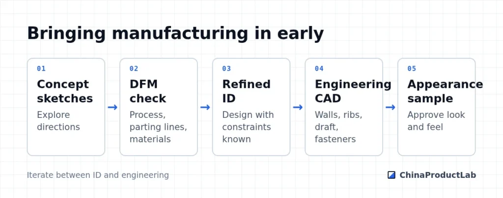
The key is to bring manufacturing knowledge in before the design is emotionally and contractually frozen. A one-hour review of a concept with a toolmaker or molder can reveal that a proposed undercut needs an expensive slide, or that a different parting line would hide the seam entirely.
Typical conflicts and solutions
| Design wish | Manufacturing reality | Common solution |
|---|---|---|
| No visible parting line | Molds need a split | Place the line on an edge or feature line |
| Perfectly vertical walls | Molds need draft to eject | Hide draft in curvature; texture-appropriate draft |
| Ultra-thin edges | Fill and strength problems | Thin visually with chamfers while keeping wall thickness |
| No visible fasteners | Parts must be held and serviced | Snap fits, hidden screws under labels or feet |
| High-gloss large surfaces | Shows every sink mark and scratch | Uniform walls, texture or coating |
Appearance models and CMF samples
Physical models resolve discussions that renderings cannot. An appearance model — machined or printed, then painted to the intended colors and finishes — shows proportions, gloss, seams and how the product feels in the hand. Use it to agree on the design before tooling and to align the whole team, including the supplier, on what “finished” looks like.
For color, material and finish (CMF), collect physical references: color chips, texture plaques, coated samples on the real substrate. Screen colors differ between monitors, and the same Pantone color looks different on glossy and textured plastic. Approved CMF samples become part of the golden sample set, so production can be checked against them. Keep a CMF sheet that lists, per part, material grade, color reference, texture, coating and print, with the sample number for each.
Keeping the design intent
Assign someone to protect the design intent through engineering — often the original designer reviewing each major CAD update. Compare engineering models with the approved renderings, and approve physical appearance samples before tooling. Differences found at that stage cost a model change; differences found at T1 cost a tool change.
Related: injection molding design rules, DFM review checklist and prototyping methods. Send your design for an early manufacturing check.