Drawings with only plus/minus dimensions leave room for interpretation: a hole can be “in tolerance” in X and Y and still not line up with its mating part. Geometric dimensioning and tolerancing (GD&T, standardised in ASME Y14.5 and the ISO GPS series) describes what actually matters — where a feature must be relative to the surfaces that locate the part. You do not need to be a GD&T expert to buy parts, but you should be able to read the common callouts and know what they cost.
The feature control frame
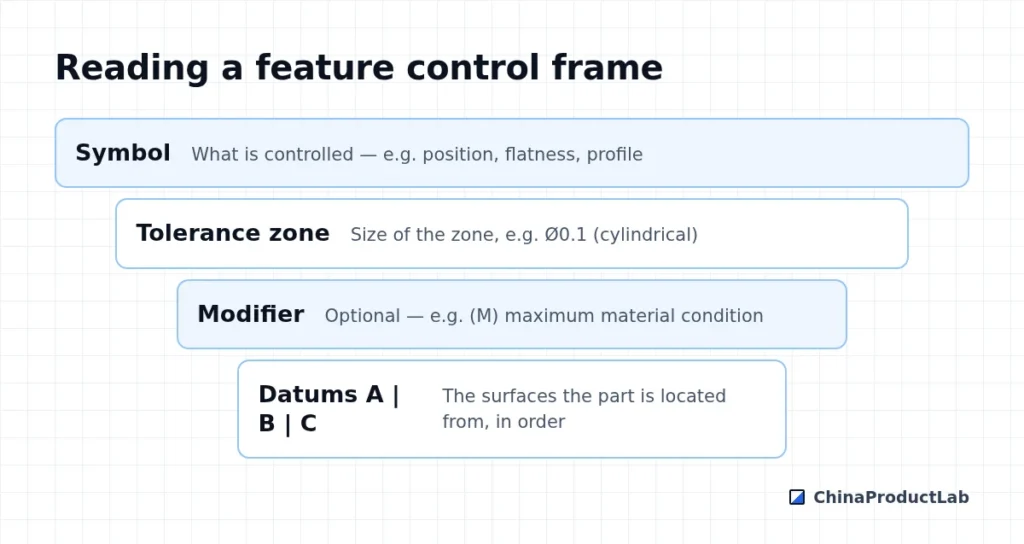
Datums are the surfaces or features the part is located from, in order of priority — typically the mounting face first, then an edge or hole. Good datums match how the part is assembled; that is what makes GD&T drawings meaningful and inspection repeatable.
Common callouts
| Callout | Controls | Typical use |
|---|---|---|
| Position | Location of a feature (hole, pin) relative to datums | Bolt patterns, alignment pins, connector cut-outs |
| Flatness | How flat a surface is, independent of other features | Sealing faces, mounting surfaces |
| Perpendicularity / parallelism | Orientation relative to a datum | Bores, guide surfaces |
| Profile of a surface | Shape and location of complex surfaces | Molded and cast parts, curved enclosures |
| Runout | Wobble of a rotating feature | Shafts, pulleys, rotating parts |
Cost and inspection
GD&T can lower cost: a cylindrical position zone allows about 57% more area than the equivalent square plus/minus zone, and the maximum material condition modifier adds bonus tolerance as holes get larger. It can also raise cost when zones are tighter than the function requires, because verifying them may need a CMM rather than calipers.
- Use GD&T on features that drive fit and function; general tolerances for the rest
- Make sure datums can be physically fixtured for inspection
- Avoid over-constraining with several callouts on one feature
- Agree the inspection method for critical callouts with the supplier
- Ask suppliers to report measured values for GD&T features in FAI reports
Common misunderstandings
- Assuming a position tolerance also controls the hole size — size is controlled separately
- Measuring from a convenient edge instead of the specified datums
- Ignoring the order of datums, which changes how the part is located
- Reading the drawing with the wrong standard — ASME and ISO interpret some rules differently
- Specifying GD&T the supplier cannot inspect, so results are guessed
When a drawing uses GD&T, write the governing standard and edition in the title block. Ask the supplier how each critical callout will be measured before production, and request one fully measured part early so that any interpretation differences surface while they are cheap to resolve.
Questions to ask when you receive a GD&T drawing
- Which datums correspond to the real mounting faces?
- Which callouts are critical to function and which are conservative?
- Can the supplier measure every callout with their equipment?
- Do the GD&T tolerances agree with the tolerance stack-up for the assembly?
Related: machining tolerances, quality control in China and CNC machining. Send your drawings for a manufacturability check.