The development kit connected across the office. The finished product, with its board inside a housing next to a battery and a metal bracket, drops connections two rooms away. Antenna performance depends on everything around the antenna — and the enclosure, battery, display and even the user’s hand are part of the radio system. Antenna planning belongs in the first layout, not after the housing is tooled.
Antenna options
| Type | Pros | Cons |
|---|---|---|
| PCB trace antenna | No part cost, compact | Needs board area and careful tuning |
| Chip antenna | Small | Very sensitive to ground plane and surroundings |
| Flexible / FPC antenna | Placed on the housing wall, away from noise | Cable and connector, placement during assembly |
| External antenna | Best range | Cost, appearance, sealing |
| Certified module with antenna | Simplifies certification | Placement rules must be followed exactly |
Placement rules
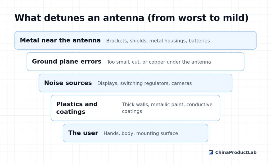
- Antenna at a board edge or corner, facing outward
- Keep-out zone free of copper and components, as specified by the vendor
- No metal parts, screws or batteries in the antenna area
- Avoid metallic paints or vacuum metallisation near the antenna
- Leave space for a matching network to tune in the final housing
Testing
Measure in the final enclosure, with the battery and all parts installed. Simple range tests show problems; over-the-air (OTA) measurements in a chamber give radiated power and sensitivity. Tune the matching network with the antenna in its housing, then lock the values. Repeat if housing material, paint or nearby parts change.
Mechanical decisions that affect RF
Many antenna problems are created by mechanical decisions made without RF input: a metal decorative ring, a battery moved to save space, a painted finish with metallic pigments, or screws placed next to the antenna. Include the RF engineer in mechanical design reviews, and maintain a keep-out zone in the 3D model so that mechanical designers can see where metal is not allowed.
Also think about how the product is used. A tracker in a pocket, a sensor bolted to a steel wall and a device held in the hand all detune antennas differently. Test in representative positions and mounting conditions, and if needed provide installation guidance — for example, a minimum distance from metal surfaces. For products sold in different variants, check that changes in housing color or material do not affect performance.
Working with module vendors
Most radio module vendors publish integration guidelines with layout examples and keep-out zones. Follow them closely, and send your layout and enclosure design to the vendor’s application engineers for review — many offer this support for free. They can often spot ground-plane or placement problems in minutes, before boards are ordered.
Certification note
Using a pre-certified radio module can simplify approvals, but only if the integration follows the module’s conditions — often including the antenna type and gain. Changes to the antenna may require additional testing. Confirm with your test lab before finalising.
Related: CE, FCC and UKCA, IoT hardware to production and IoT hardware.